Test, Measurement and Analysis Tool for RME Interfaces
RME interfaces not only provide you with a professional digital audio interface, but also with a unique software tool: DIGICheck, the incredible utility for test, measurement and analysis of the digital audio data stream.
This TECH INFO describes the functions and the technology used in DIGICheck. Please be aware that DIGICheck works with Windows and Mac OS X, but only with hardware from RME. This is due to special implementations within the hardware, that aren't available with any other card. RME interfaces are based on RME's own chip design (realized in a FPGA). Because of this you won't find any other card in the market that gives you a Channel Status display, a 100% accurate 24-Bit level meter, a decoding of the CD-subcode, and hardware based RMS calculations.
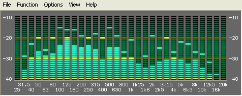
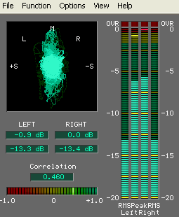
A description of DIGICheck's latest additions, Totalyser, Spectral Analyser and Vector Audio Scope, can be found here.
Technical background: the 32 bit technology
To our knowledge, RME's DIGI96 series was the first audio card ever to allowed the record of the complete 32 bit digital audio data stream. Besides the usual 24 audio bits P, C, U and V bits are also transmitted. That's 28? Right, the first 4 bits form the preamble. This synchronization signal isn't needed anymore after a successful receiving and decoding of the signal. To use the data of the PCUV-bits the start of the block must be known. Therefore the data stream sent to the record program also includes the CBL (channel block start) signal since the introduction of the DIGI96 series.
A detailed description of the used transfer format can be found in the TECH INFO Track Marker Support.
The Software DIGICheck
The software is very easy to use, well designed, useful, and includes many valuable options. A detailed online help and technical reference is also included.
After the first start the program asks for the 'Record Device' (data source) and the kind of font and size for screen presentation. Both can be configured at a later time too. A small display with a good overview is achieved using Arial 8, else Arial 10 is recommended. These and all other settings are stored in Windows' registry.
In the beginning DIGICheck worked like any other record software, opening one or multiple devices for recording, but not writing the incoming data to disk. Therefore DIGICheck only worked as long as no other record program used the selected devices.
Since Hammerfall and Hammerfall DSP, DIGICheck uses the multiclient drivers of the interface to access record and playback (!) data. This happens competely in the background, in parallel to any (!) currently active audio software.
Each function allows to optimize and store the size and position of its window. The configuration of the Level Meters is done via F2 or a menu entry. The Channel Status Display may be printed, 'Deactivate Screensaver' and 'Always on top' sure don't need to be explained.
The Functions in DIGICheck
Level Meter
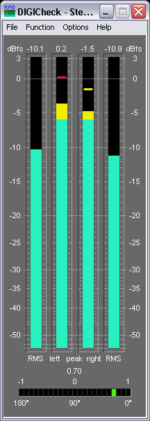
This function provides highly precise level meters with 24-Bit resolution. All parameters like range, resolution and color are completely configurable without limitations in 'Level Meter Setup'. Because of the highly configurable parameters the Level Meter is ready for a great number of applications:
- Peak level measurement
- RMS level measurement
- Over detection
- Measurement of the correlation (phase)
- Measurement of dynamic and signal to noise ratios
- Display of the difference between RMS and Peak (volume)
- Long term peak detection
The peak level (AC+DC) is shown in the inner bars. Every single sample is used for computing Peak level and RMS level. A single sample is sufficient for a 0 dBFS readout. Overs are indicated when more than a user defined count (1 to 20) of consecutive full scale samples occur. A Peak Hold function with adjustable hold time (0.2 s to 100 s) is also implemented.
The RMS level (only AC) is shown in the outer bars. The reference (0 dBFS) is a sine with digital full scale level. This allows easy comparisons of RMS and Peak with usual signals. The RMS display is based on a mathematical true calculation of the root mean square, and will therefore display highly (!) accurate values.
For example: Play back the file crest_16.wav (found on our download page or on the RME Driver-CD) using the DIGI96, connect output to input (Clock Mode Master!) and start the Level Meter. It shows a peak value of 0 dBFS, but a RMS-value of only -16,1 dBFS. Every measurement device based on usual analog RMS detectors will come in big trouble confronted with such a high Crest value (ratio peak to rms) and will show wrong values around -6 dB.
Thanks to 24-Bit the meters break down the lower barrier. Finally you are enabled to see the real dynamics of your equipment! And we don't make jokes: The RMS levels shown from DIGICheck equal exact (!) the values measured by 10.000$ audio measurement systems! To be more specific they equal RMS unweighted, which means RMS without any special weighting filter. To achieve a better readability at lower noise levels we recommend to set the release rate to 10 dB/s (or to use the Bit Statistic instead, see below).
Multichannel Level Meter
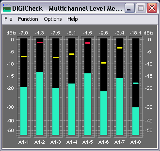
Besides the 2-Channel level display also an 8-Channel level display is available. This Multichannel Level Meter uses the same settings options as the 2-Channel Level Meter. The bar can be set to display RMS or Peak.
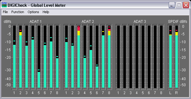
Global Level Meter
DIGICheck's Global Level Meter displayes all available channels of the the interface simultaneously. This function is mainly intended as fast overview of current configuration and input signals. Channels with invalid input signals will be greyed out.
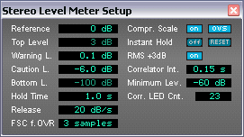
Level Meter Setup
The visible display range can be set between 0 and -160 dBFS. The measurement includes the whole range available from the received audio bit resolution, displayed in 0.1 dB steps. The change in color is defined in 'Warning Level'. Set to 0 dB a color change is only performed on the highest peak hold step - when 'Over' is detected. The number of consecutive full scale samples for an 'Over' indication can be defined between 1 and 20. As the display of a phase relationship makes no sense below a certain threshold the correlator's display will be turned off. The number of LEDs in the Correlation Meter is also configurable in a wide range.
Channel Status Display / User bits
This function decodes and displays the channel status information contained in the SPDIF signal. In addition the real sample rate is measured with an accuracy of ± 100 Hz. A printing function provides a hardcopy of the channel status.

Even if you're not a super-duper technician you can gain useful information from this table. Incompatibilities among digital devices are explained by a set 'Emphasis' or an active copy protection (field 'SCMS'.) No sound from the CD-player? Perhaps the CD is full of scratches, showing 'Data Invalid' (resulting in an automatic mute of the DA-converter.)
When connecting a CD-player or a DAT-recorder parts of the subcode (coded into the user bits) will be shown in the 'Validity-Bit' field. The name changes to 'Validity-Bit/CD-Subcode' or 'Validity-Bit/DAT-Subcode' and shows track number, index and current play time. From the DAT's subcode the Start-ID (not track number!) is presented whenever one occurs. Of course ALL information in the subcode may be decoded thanks to the 32 bit mode of the DIGI96 series, but this is only an example. A professional hard disk recording software might use this information when transferring a 2 hour DAT tape into the PC to automatically set markers at the begin of each track (at each Start-ID.)
Bit Statistic & Noise
This function shows the state of the audio bits. Three states are detected: always low (0), alternating and always high (1.) Alternating means the bit is in use, zero indicates unused bits and permanent one is often caused by a defective AD-converter.

The Bit Statistics allows to determine the real resolution or word length of audio signals, for example at the output of A/D-converters, mixing desks and effects devices. Audio data will be indicated green (normal, bit used), otherwise blue (permanent 0, bit not used). In case of permanent 1 (error or DC) the color changes to red. The normal state of the Channel Status bit and the Validity bit is green, permanent values (red) indicate an error or distorted audio data.
Glossary
Crest value: Ratio between peak and RMS value. Music with small crest value is louder than one with a high crest value.
dBFS: deci Bel Full Scale. Logarithmic level ratio referenced to digital full level (7FFFH / 8000H).
RMS unweighted: Root Mean Square measurement without special weighting filter, measures flat within 22 Hz to 22 kHz.
Sample frequency: Number of samples taken from the analog signal per second.
Word length: Same as bit resolution. Number of bits per sample. 16-Bit: 65536 steps or 96 dB dynamic range.


