Theory
Usually a clock section consists of an analog PLL for external synchronization and several quartz oscillators for internal synchronisation. SteadyClock requires only one quartz, using a frequency not equalling digital audio, therefore effectively avoiding disturbances. Latest circuit designs like hi-speed digital synthesizer operating at unsurpassed 200 MHz, a fully digital PLL design, and efficient analog filtering allow RME to realize a completely newly developed clock technology, right within the FPGA, at lowest costs. The clock's performance exceeds even professional expectations. Despite its remarkable features, SteadyClock reacts quite fast compared to other techniques. It locks in fractions of a second to the input signal, follows even extreme varipitch changes with phase accuracy, and locks directly within a range of 28 kHz up to 200 kHz.
Compared to other technologies, one of SteadyClock's main advantages is its single stage design. Usually the PLL consists of a first stage reacting as broad clock locking circuit, then a second stage acts as narrow locking circuit. Only the narrow circuit provides jitter suppression, so that locking takes some time, and in varipitch applications, where the second stage does not get active at all, nearly no jitter suppression is provided. SteadyClock locks directly and provides high jitter suppression throughout!
Measurements
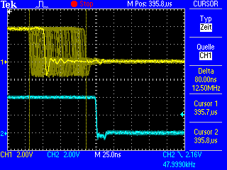
SteadyClock has originally been developed to gain a stable and clean clock from the heavily jittery MADI data signal. The embedded MADI clock suffers from about 80 ns jitter, caused by the time resolution of 125 MHz within the format. Common jitter values for other devices are 5 ns, while a very good clock will have less than 2 ns.
The picture to the right shows the MADI input signal with 80 ns of jitter (top graph, yellow). Thanks to SteadyClock this signal turns into a clock with less than 2 ns jitter (lower graph, blue).
Using other input sources like AES, SPDIF, word clock or ADAT, one most probably never experiences such high jitter values. But SteadyClock is not only ready for them, it would handle them just on the fly.
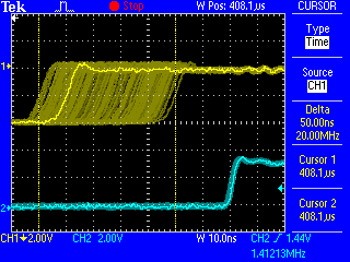
The screenshot to the right shows an extremely jittery word clock signal of about 50 ns jitter (top graph, yellow). Again SteadyClock provides an extreme clean-up. The filtered clock shows less than 2 ns jitter (lower graph, blue).
Real-world Operation
The following example shows SteadyClock's behaviour in real-world operation. The ADAT input of the HDSP 9632 uses an advanced Bitclock PLL. But this PLL does not provide any jitter suppression within the audio range. Therefore the quality of the clock extracted from the ADAT signal depends on the specific ADAT source.
But on the HDSP 9632 (also ADI-648 and HDSP MADI), SteadyClock will process the ADAT clock signal after its extraction.
The picture to the right shows the word clock output of the HDSP 9632, which is directly fed from the internal master clock - and with this from SteadyClock.
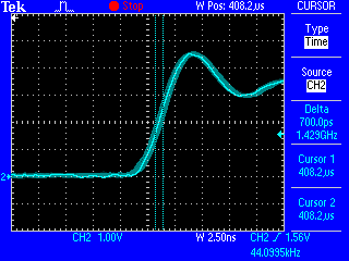
In this case the card is set to AutoSync, and receives an ADAT signal with very low jitter (below 1 ns). The remaining jitter behind BitClock PLL and SteadyClock is hard to detect at all, with a value of around 700 ps (0.7 ns).
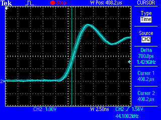
This picture shows the same situation with an ADAT signal of about 40 ns of jitter. The input jitter is nearly completely removed, the output of the HDSP 9632 again shows around 700 ps (0.7 ns).
The signal processed by SteadyClock is used internally to clock on-board AD- and DA-converters, and to clock the digital outputs. Additionally it is available directly at the word clock outputs.
Measurement using Audio Precision System Two
We tested SteadyClock using an Audio Precision System Two audio test system. The AP was connected to an ADI-4 DD, as the AP can measure jitter only on AES inputs and outputs. SteadyClock is used in the ADI-648, ADI2, HDSP MADI, HDSP 9632 and Fireface 800. The measurement results are valid for all the mentioned units as well.
The AP generated an AES signal which had been modulated with 10 ns, 20 ns, 50 ns and 100 ns jitter. The jitter frequency was not fixed, but changed in 401 steps between 20 Hz and 100 kHz. This way, a diagram was generated which shows the remaining jitter related to the jitter frequency, or in other words the amount of jitter reduction relative to the jitter frequency.
Doing a loopback selftest, we found that the AP only measures exactly within the range 50 Hz to 50 kHz, so we limited the test results to this range.
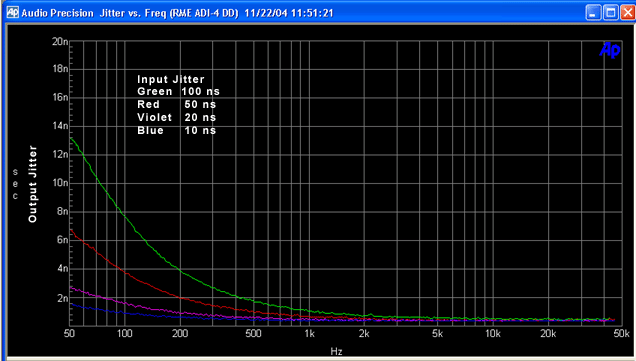
The diagram shows that even outside the expected filter range, SteadyClock heavily reduces jitter. An input jitter of 100 ns modulated by 50 Hz is brought down to 14 ns, at 100 Hz it is only 7.5 ns. Already at 500 Hz the remaining jitter is always below 2 ns, and looking at more real-world values like a 10 ns input jitter, the output jitter stays below 1 ns nearly all the time! Also the advertised value of 30 dB reduction at 2.4 kHz turns out to be an even better 'more than 40 dB'!
This measurement shows that SteadyClock can not only compete with other known jitter reduction techniques, but in fact is able to outperform them easily in several regards, like efficiency, speed, ease of use and costs.
Conclusion
The SteadyClock technology of RME's latest products guarantees an excellent performance in all clock modes. Its highly efficient jitter suppression enables ADI-648, HDSP 9632, HDSP MADI, ADI-2, ADI-4 DD and Fireface 800 to refresh and clean up any clock signal, and to provide the clock signal as reference clock at the word clock output. At the same time, analog conversion is performed on a guarateed level of highest quality, completely independent from the kind and quality of the used reference clock. The cleaned and jitter-freed clock signal can be used as reference clock in any application. And the quality of the external (input) clock doesn't matter anymore.
Copyright © Matthias Carstens.
All entries in this Tech Infopaper have been thoroughly checked, however no guarantee for correctness can be given. RME cannot be held responsible for any misleading or incorrect information provided throughout this document. Lending or copying any part or the complete document or its contents is only possible with the written permission from RME.

